
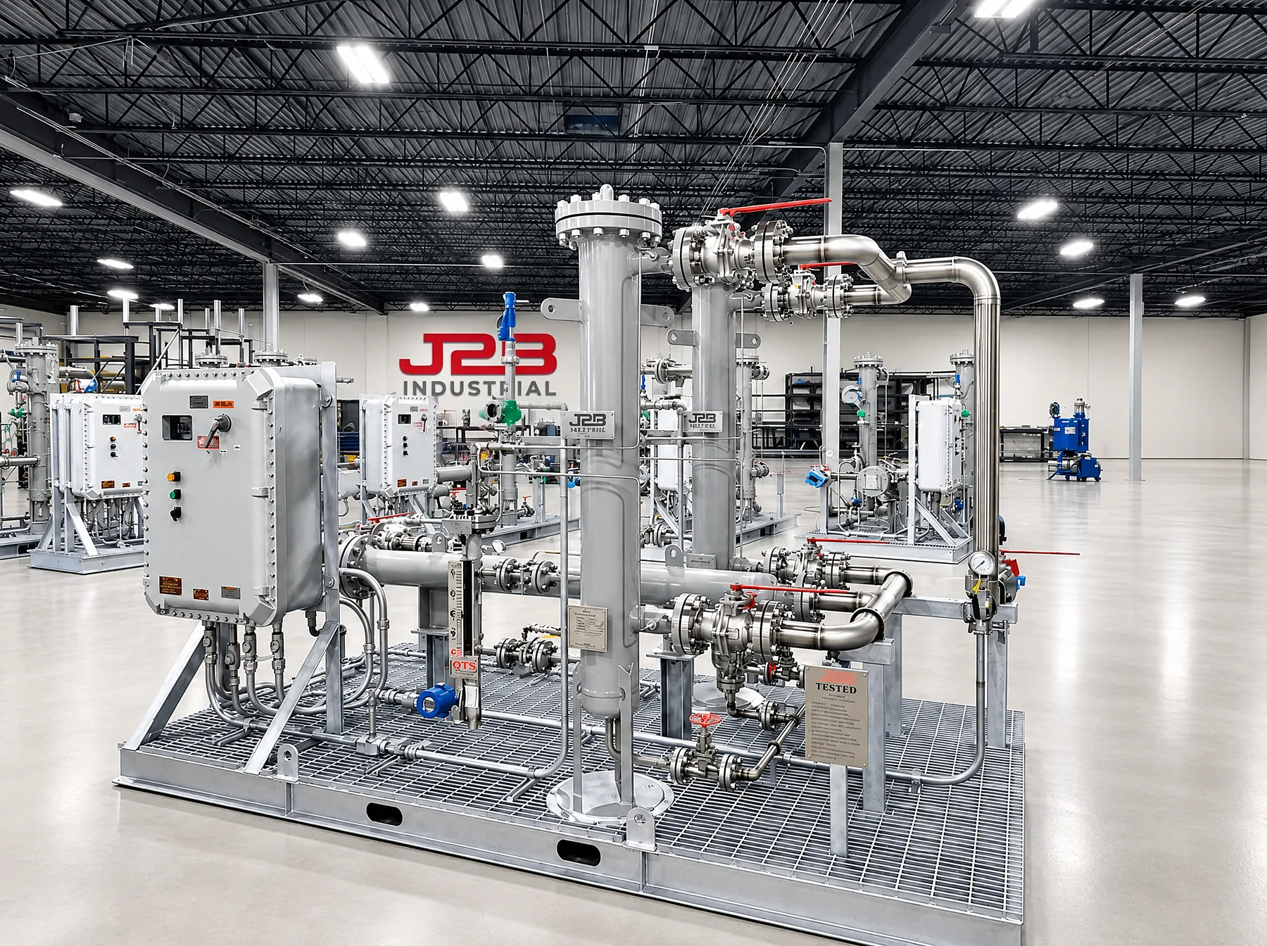
For aero-derivative, industrial and frame gas turbines
Fuel Gas Conditioning Systems
Engineered around the turbine OEM's governing fuel gas requirements and operating envelope, to protect the turbine fuel system while holding the required gas condition: filtration, liquid removal, pressure, temperature, dew point margin and required superheat.
Inside the package
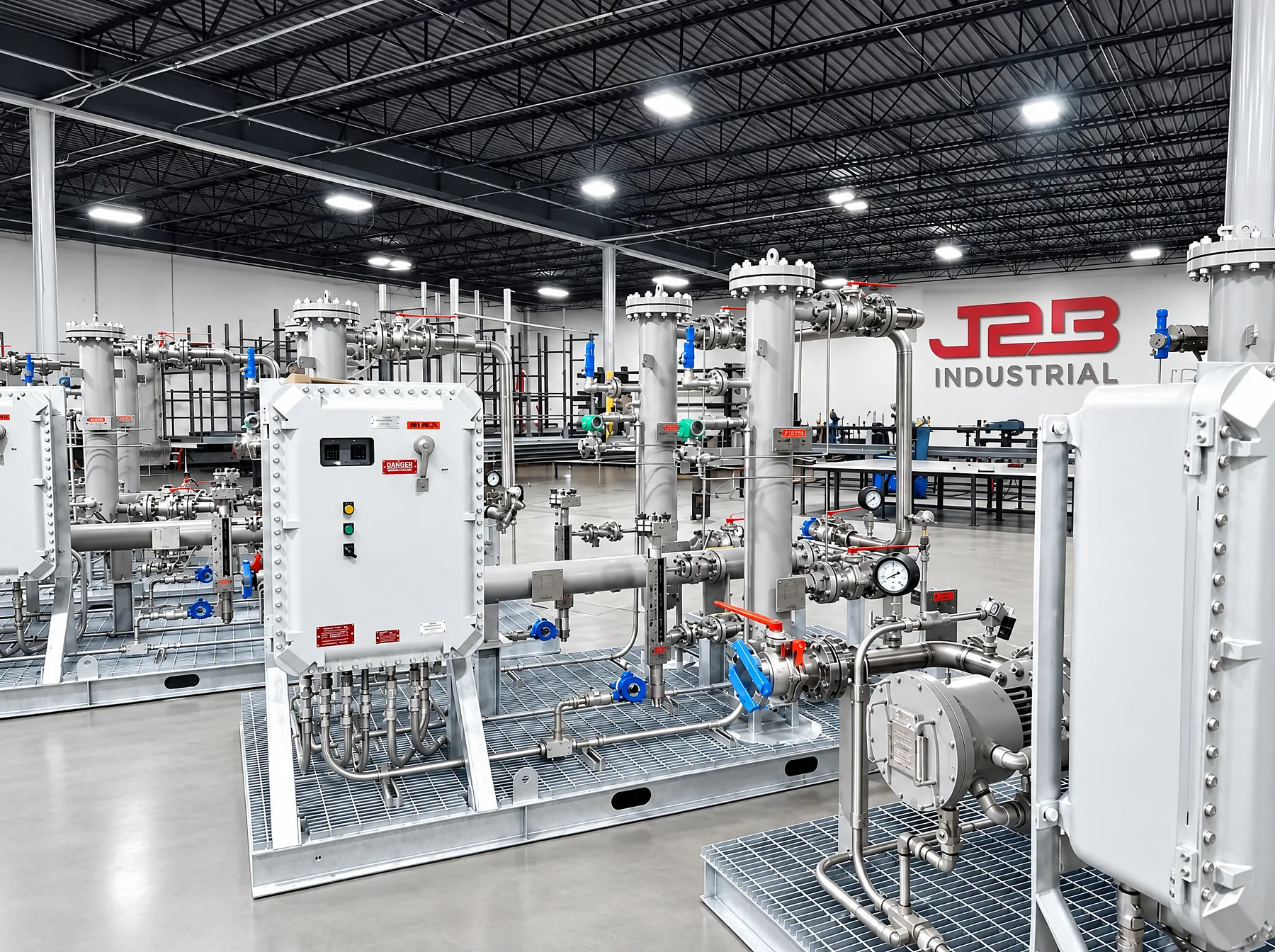
One process train, integrated and tested on one skid.
Select a component. Simplified schematic; tag numbers are illustrative and each package is configured to its turbine and gas.
Engineered around the turbine and the site
Every package starts from the turbine and the gas it will burn. These inputs set vessel sizes, heater duty, regulator configuration, instrumentation and the electrical design.
| Design input | What it determines |
|---|---|
| Gas composition | Site gas analyses: composition, heating value, water content and contaminants |
| Flow range | Fuel flow from start and minimum load through full load and trip |
| Operating pressure | Supply pressure range at the inlet and the pressure required at the turbine gas control valve |
| Inlet and outlet temperature | Coldest supply temperature and the temperature window the turbine accepts |
| Filtration and liquid removal | Particle and aerosol removal to the OEM rating, and the liquid carryover to be handled |
| Water and hydrocarbon dew point | Dew points across the supply range, which set heating duty |
| Required superheat margin | Margin above dew point the OEM requires at the gas control valve |
| Electrical area classification | Hazardous-area rating for heaters, instruments, panels and wiring |
| OEM fuel gas requirements | The turbine manufacturer's governing fuel gas specification |
| Site operating conditions | Ambient range, altitude, utilities available and footprint |
One turbine, or a standardized fleet.
J2B can design for a single installation or standardize a common platform across an entire fleet. For a fleet, the configuration is proven on a first article, released at a controlled revision and repeated unit after unit, so the hundredth package matches the first.
By turbine class
| Aero-derivative | Industrial | Frame | |
|---|---|---|---|
| Typical service | Fast-start peaking, bridge and prime power; many data center fleets | Distributed generation, cogeneration, mechanical drive | Utility simple cycle and combined cycle |
| Fuel pressure | Higher supply pressure requirement | Moderate | Varies by frame and combustion system |
| Package emphasis | Pressure control response and tight temperature control through transients | Liquid removal and dew point margin on variable supply gas | Capacity, redundant filtration and heating runs, superheat control at high flow |
| Combustion sensitivity | Lean-premixed DLE combustors are sensitive to fuel composition and liquids | DLE/DLN or diffusion, per model | DLN combustors are sensitive to liquids and heavy hydrocarbons |
General characteristics. Each package is engineered to the specific turbine model and its OEM fuel gas requirements.
Across the package
Documentation per unit
Engineering
- Process design basis and sizing
- P&IDs and general arrangement
- Bill of materials and instrument index
- Cause and effect matrix
- Control narrative
Quality
- Weld map, WPS, PQR and welder qualifications
- Material test reports with heat traceability
- NDE reports where required
- Pressure test records
- Instrument calibration data
Turnover
- FAT procedure and signed report
- Manufacturing Record Book
- As-built drawings at released revision
- Installation, operation and maintenance manuals
- Spare parts list
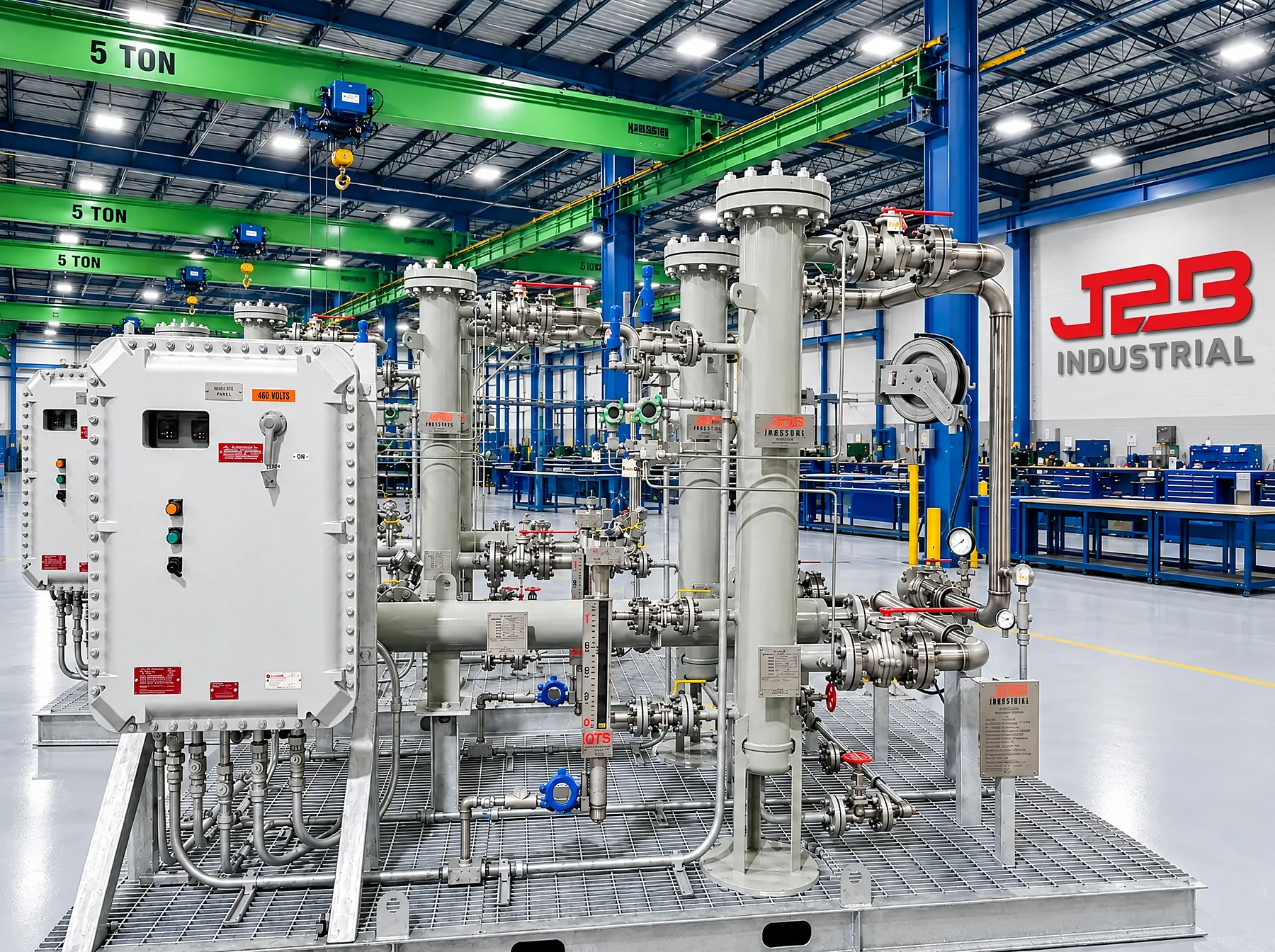
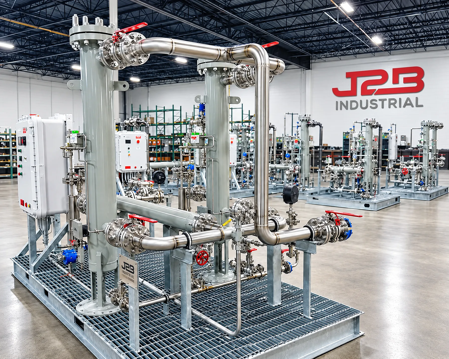
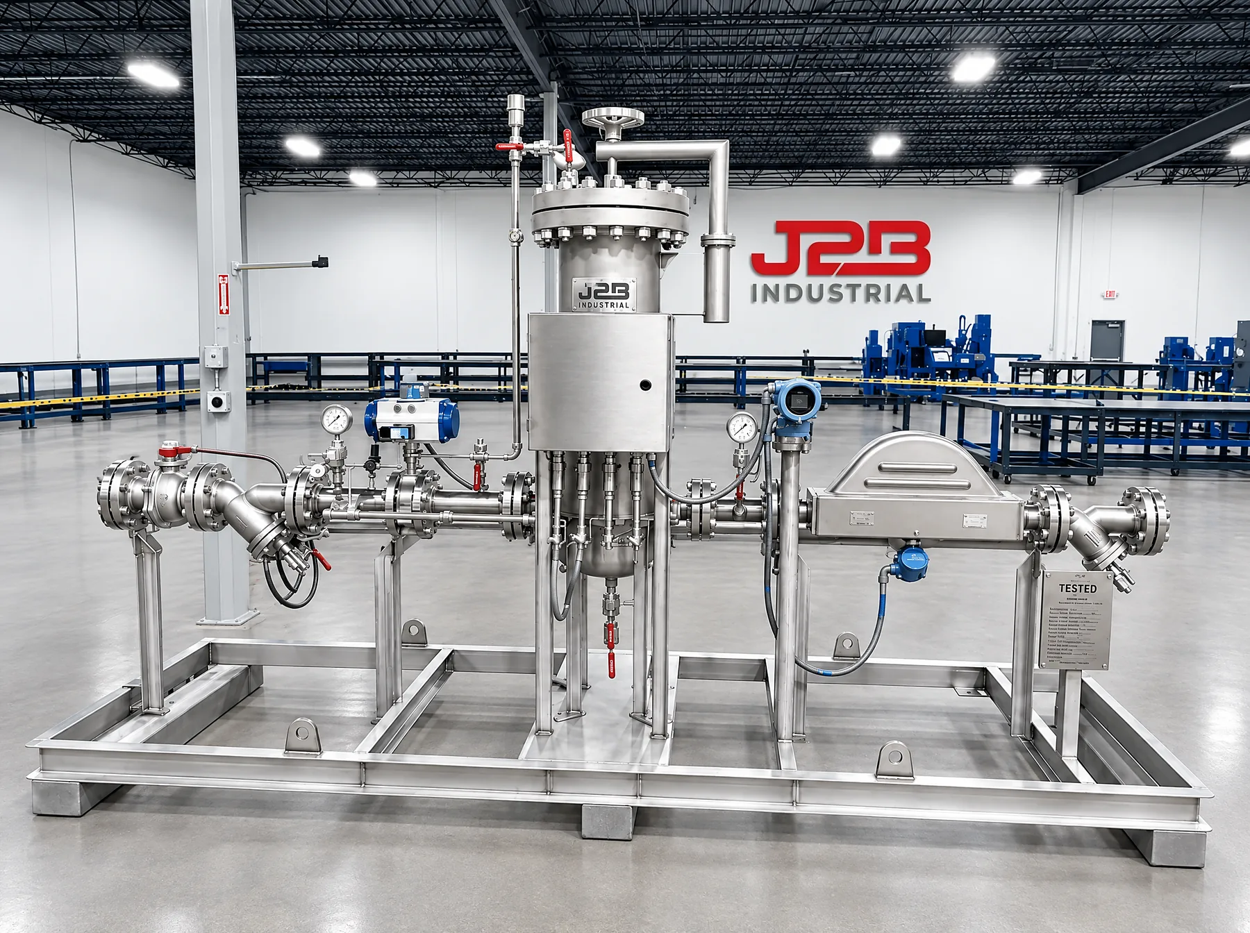
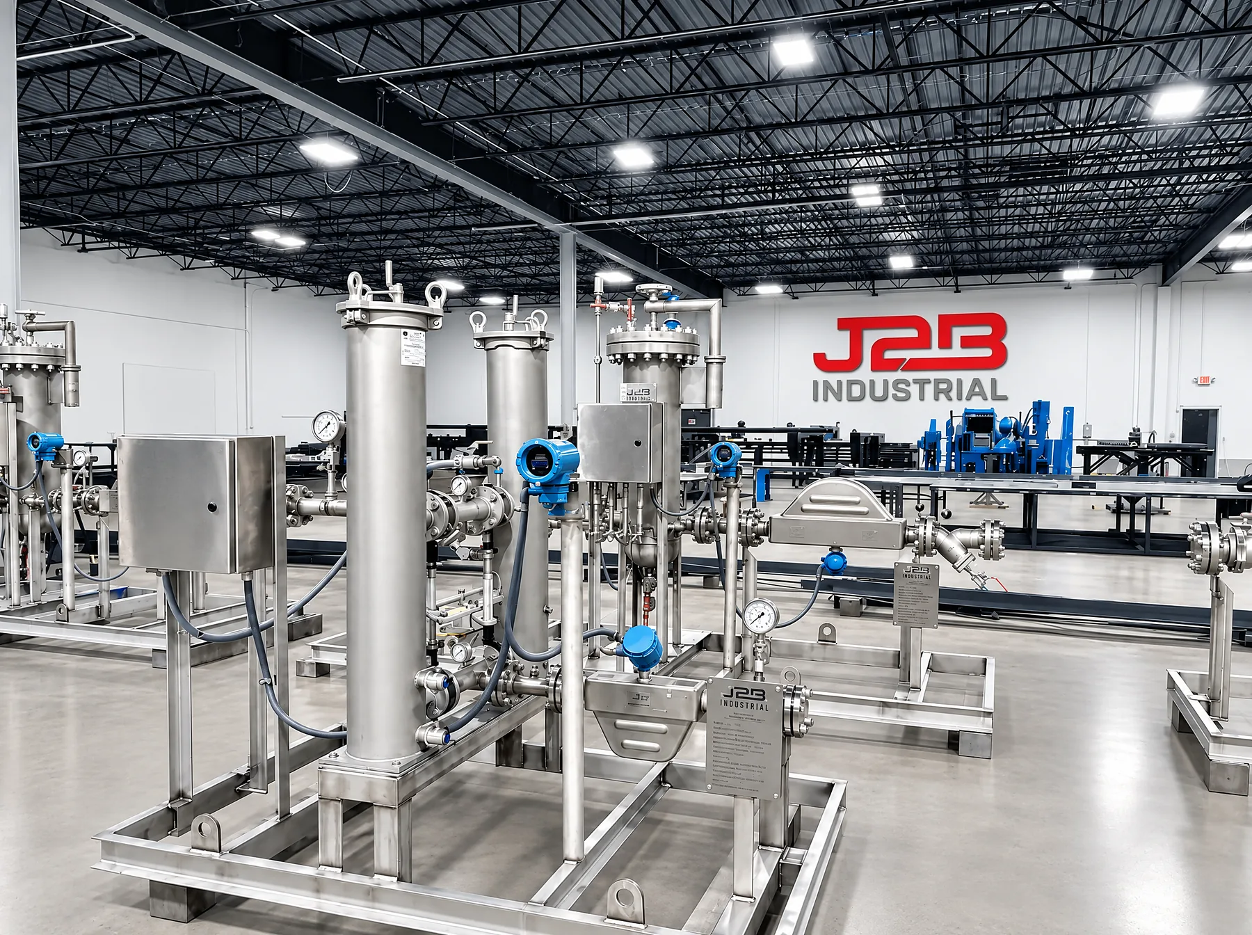
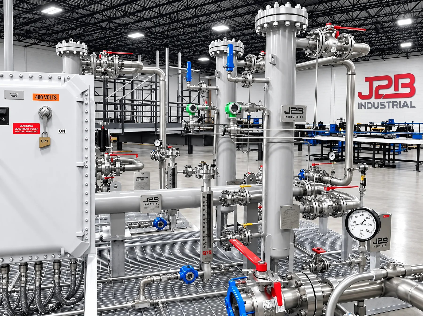
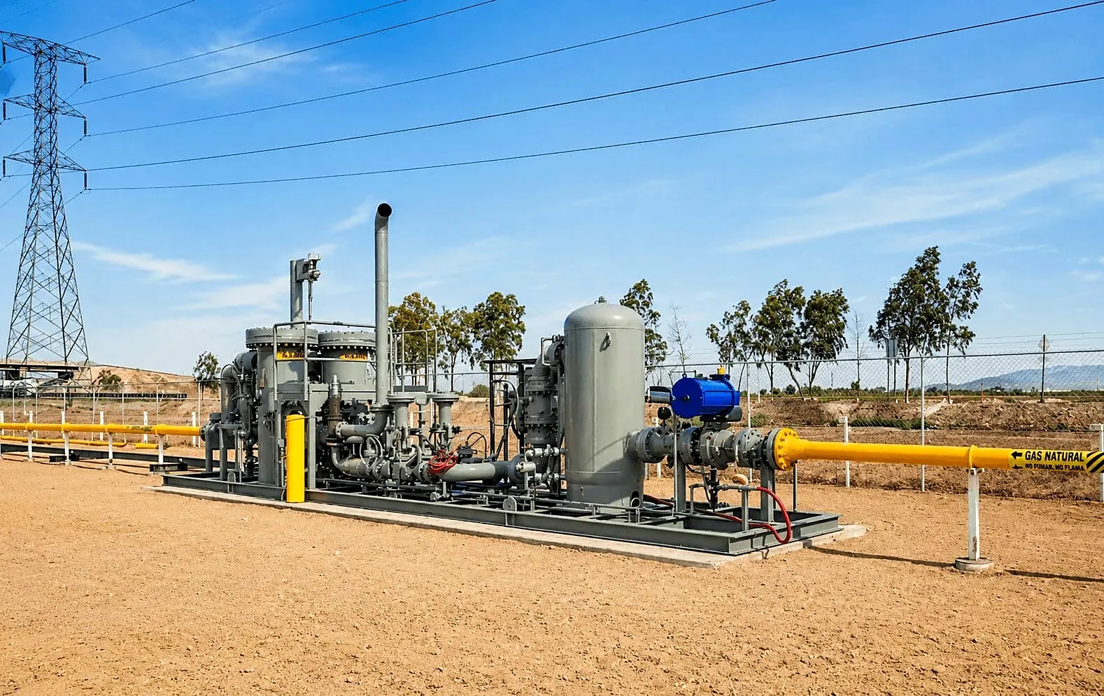
Fuel gas skids at J2B
Questions engineers ask first
What does J2B need to engineer a fuel gas conditioning system?
The turbine model and quantity, the OEM's governing fuel gas requirements, one or more site gas analyses, the flow range, operating pressure, inlet and outlet temperature, the required dew point and superheat margin, the electrical area classification and the site operating conditions.
Which gas turbines does J2B build fuel gas conditioning for?
Aero-derivative, industrial and frame gas turbines. Each package is engineered around the turbine OEM's governing fuel gas requirements and operating envelope.
Can one design serve an entire fleet?
Yes. J2B can adapt the system to a single turbine configuration or develop a standardized platform for a multi-unit fleet: the design is frozen after a first article passes every inspection and a full Factory Acceptance Test, then built as identical serial-numbered units under configuration control.
What capacity range do J2B gas conditioning systems cover?
J2B supports gas conditioning and heating systems from approximately 7,500 lb/hr to more than 100,000 lb/hr (about 3,400 to more than 45,000 kg/h).
Why is fuel gas heated before it reaches the turbine?
Heating keeps the gas above its hydrocarbon and water dew point so no liquid forms as it cools or as its pressure drops across the regulator. GE Vernova's GER-3620P describes a margin of about 50 degrees F (28 degrees C) above the hydrocarbon dew point at the gas control valve, with the exact value calculated under the OEM specification.
Let's build your next program.
Whether you are developing a single installation or planning a fleet deployment, J2B Industrial can work with your team to develop an engineered, manufacturable solution and establish the production capacity required to support your schedule.
Or call (904) 574-8919 · sales@j2bindustrial.com
Design basis or specification ready? Send your design basis