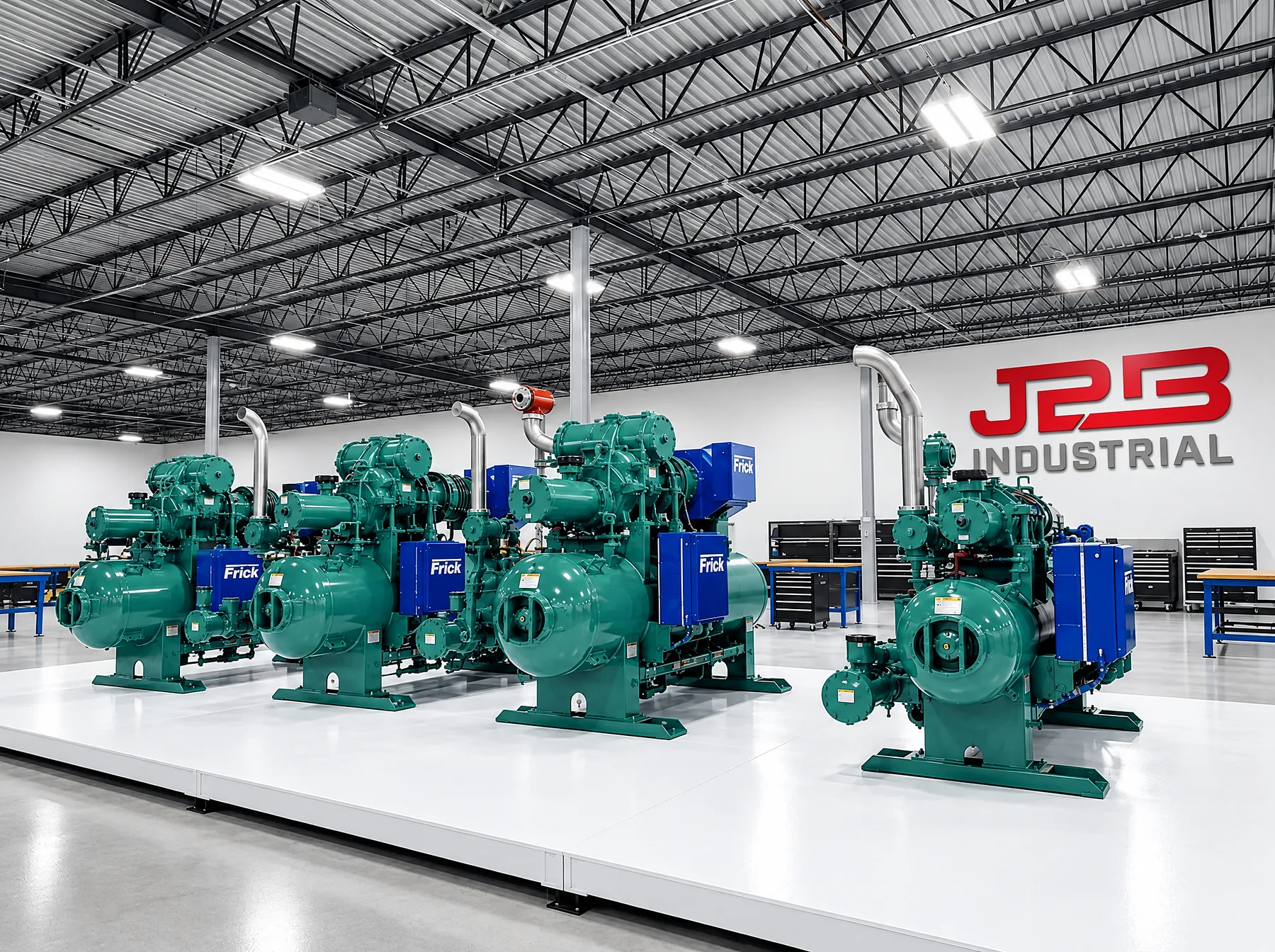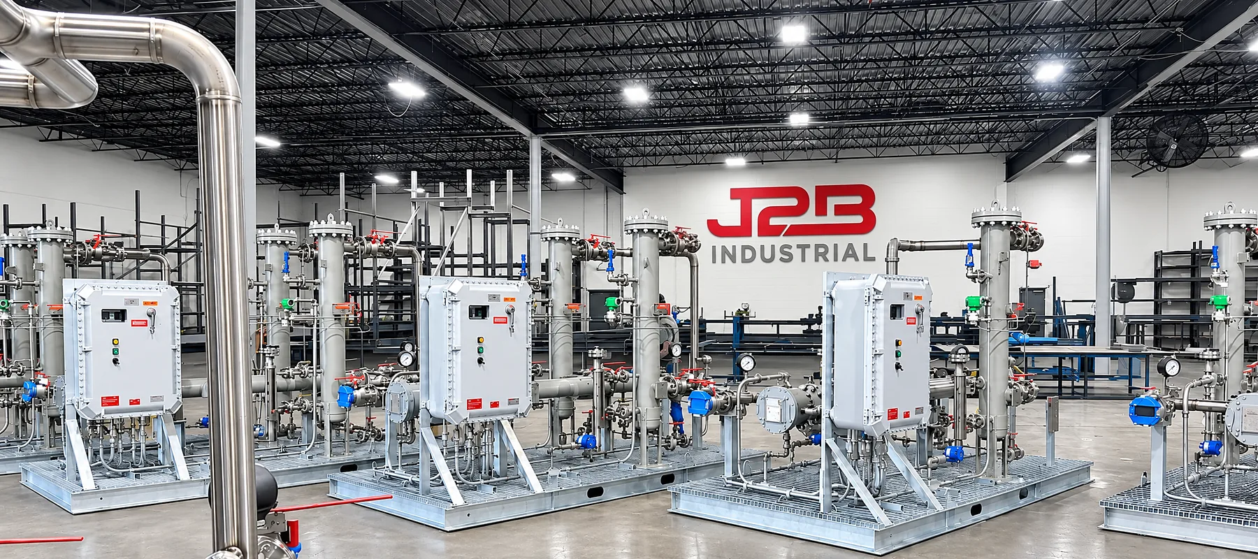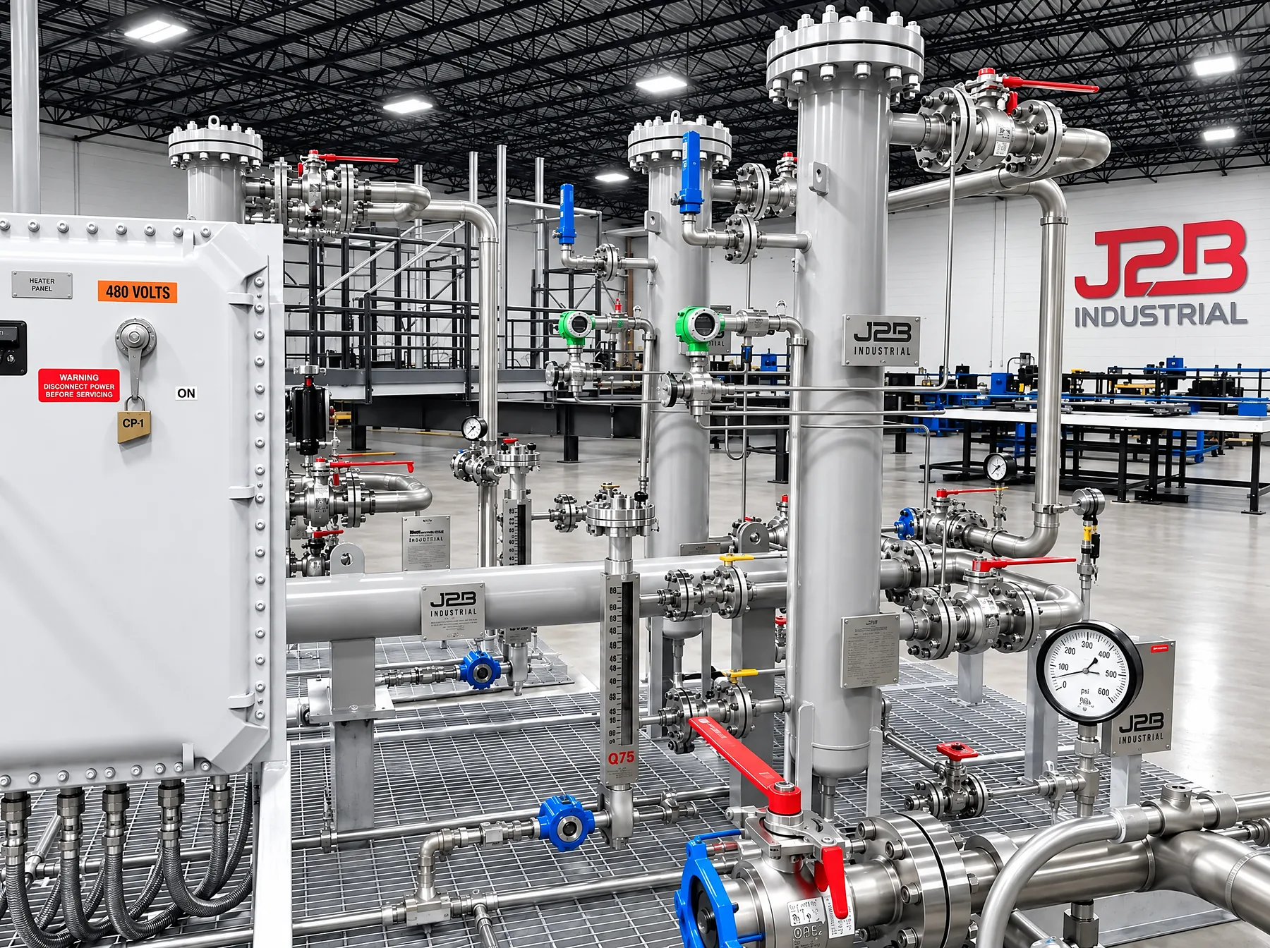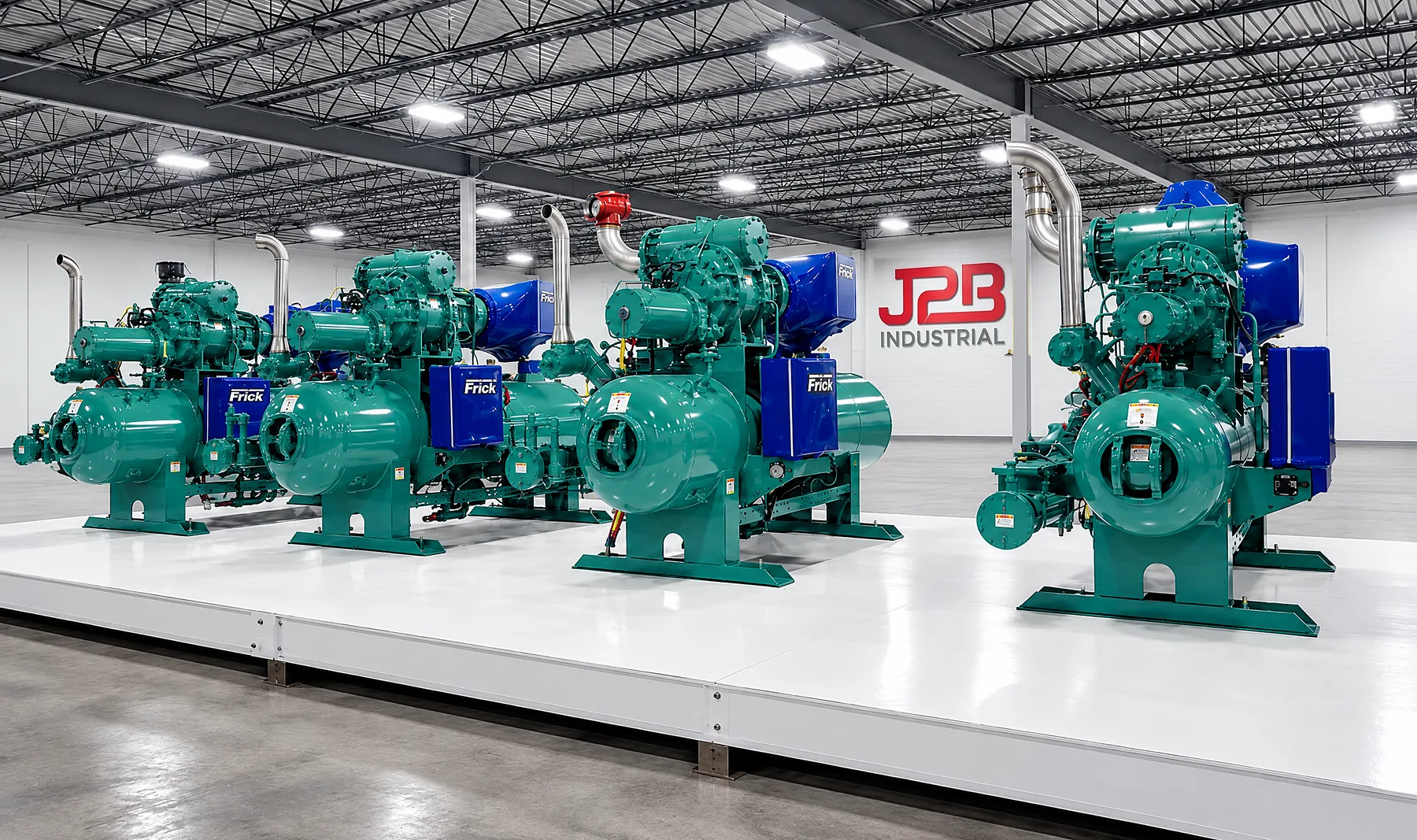
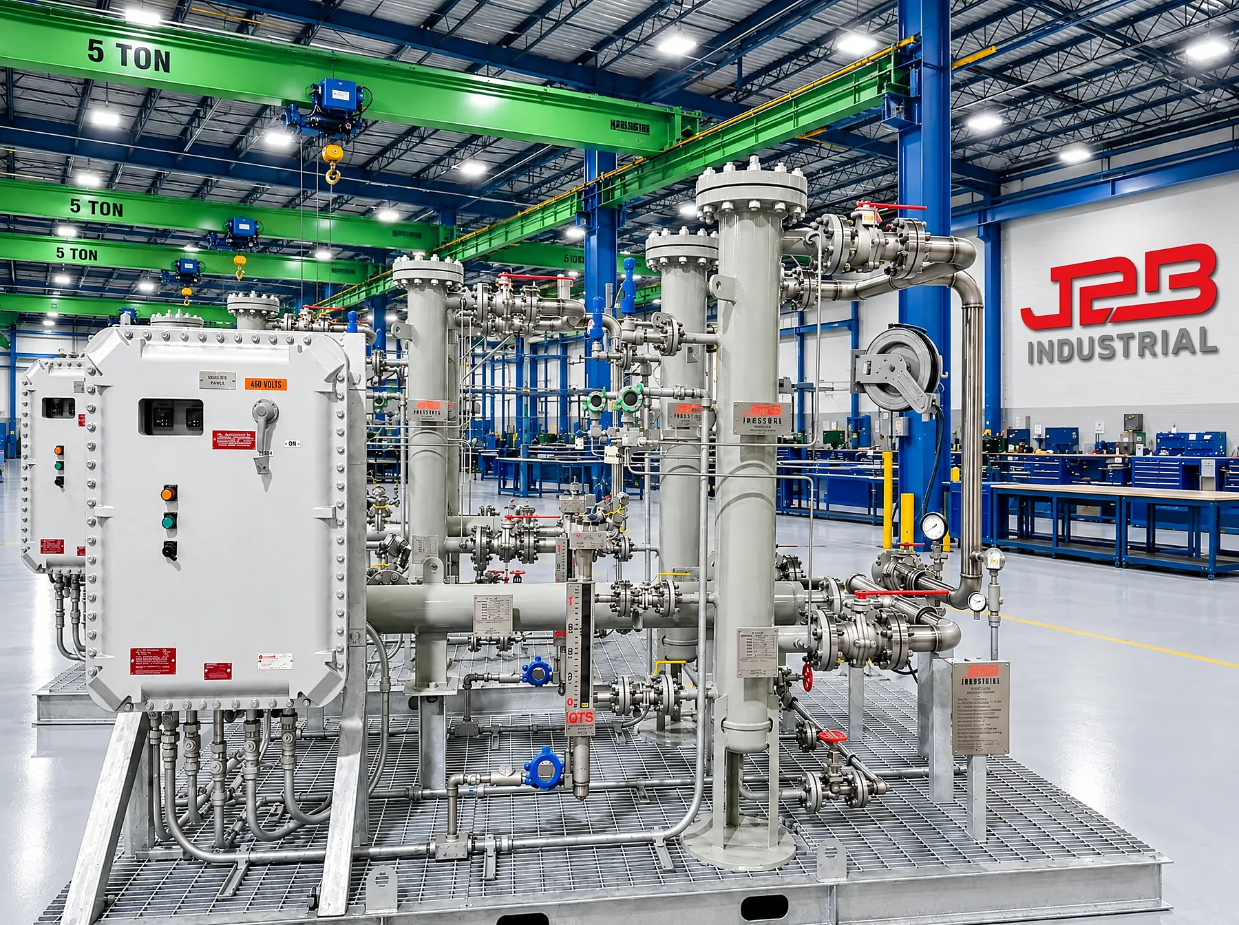
A gas turbine burns whatever arrives at its fuel control valve. Pipeline gas is rarely as clean, dry or stable as a turbine's fuel specification requires, and the gap between the two is what a fuel gas conditioning system closes. It sits between the site gas supply and the turbine and delivers gas at a controlled pressure and temperature, free of liquids and particulates.
Why turbines need conditioned gas
Turbine manufacturers publish fuel gas specifications, and meeting them is tied to warranty. GE Vernova's operating and maintenance reference, GER-3620P, states that following its gas fuel specification (GEI-41040) is required for proper combustion operation and to keep applicable warranties.1
The same document describes what happens when fuel carries liquids. Liquid hydrocarbon carryover can drive hot gas path hardware into severe overtemperature, which can sharply shorten parts life or repair intervals. It can also move the flame upstream in the combustion chambers, which can cause severe damage to combustion hardware.1 In lean-premixed dry low emissions combustors, fuel composition also affects dew point and superheat requirements, flashback and combustion stability.2
Particulates cause a separate set of problems: plugged fuel nozzle passages, eroded valve internals and combustion hardware, and damage to first-stage nozzles.
The conditioning train
A typical system arranges its equipment in the order the gas needs it. The exact configuration depends on the gas and the turbine, but the functions are consistent.
| Stage | Function |
|---|---|
| Inlet isolation and shutdown valve | Fail-closed isolation at the package boundary, tripped by the safety shutdown system |
| Scrubber or separator | Removes free liquids and slugs ahead of fine filtration |
| Filter/coalescer | Removes fine liquid aerosols and particulates to the OEM filtration rating |
| Flow measurement | Meters gas to the accuracy the project requires |
| Fuel gas heater | Raises temperature to hold superheat above dew point and to meet the turbine fuel temperature window |
| Pressure reduction | Holds turbine inlet pressure through start, load change and trip |
| Outlet shutdown valve | Final isolation to the turbine, interlocked with the inlet valve and vent |
| Collection tank | Receives drained liquids from vessel sumps, with level alarms |
| Controls and safety system | PLC control, alarms and shutdown logic built from the cause and effect matrix |
GER-3620P names effective gas scrubbers and coalescing filters upstream of the performance gas heaters as best practice for removing liquids.1
Dew point and superheat
Gas that is exactly at its dew point will condense the moment it cools, and gas cools every time its pressure drops. The Joule-Thomson effect across a pressure regulator can take gas that was dry upstream and produce liquid downstream. That is why fuel gas is heated, and why heating is usually placed ahead of the pressure reduction that would otherwise cool it.
GER-3620P describes superheating fuel gas to about 50°F (28°C) above the hydrocarbon dew point, measured at the turbine gas control valve connection, with the exact requirement calculated under GEI-41040.1
Other manufacturers publish their own requirements. Solar Turbines' fuel specification ES 9-98 is one example.3 A conditioning system is designed to the specification of the turbine it serves, not to a generic margin.
Sizing inputs
A fuel gas conditioning package is engineered from a short list of inputs. Missing or optimistic inputs are the most common reason a package underperforms in the field.
- Turbine model and count, with fuel flow at minimum load, full load and peak
- Applicable OEM fuel gas specification, including superheat, filtration and temperature limits
- Site gas analysis, ideally several, covering composition, heating value, contaminants and water content
- Supply pressure and temperature range, including worst-case low pressure
- Required turbine inlet pressure and allowable pressure fluctuation
- Ambient range and area classification for the site
- Redundancy philosophy: single run, monitor run or N+1 across heaters and filters
Conditioning at fleet scale
Data center power plants are increasingly built from many identical packaged units rather than one large machine. GE Vernova's announced delivery of 29 LM2500XPRESS units to Crusoe is one example; each package includes the turbine, a gas compressor and emissions control.4 VoltaGrid's plan for Oracle uses 92 power packs of about 25 MW each.5
When the generation is a fleet, the fuel systems serving it benefit from the same approach: one engineered configuration, proven on a first article, then built repeatedly with configuration control, so every unit on the site behaves the same way and spares are common across the fleet.
- GE Vernova, GER-3620P, Heavy-Duty Gas Turbine Operating and Maintenance Considerations, Rev P, 01/2021. gevernova.com
- Blouch et al., ASME GT2011-45387, on fuel flexibility in GE aero-derivative DLE combustors. PDF
- Solar Turbines ES 9-98, Fuel, Air and Water (or Steam) for Solar Gas Turbine Engines, as cited in state air permit filings.
- GE Vernova press release, 22 July 2025. gevernova.com
- POWER Magazine, 15 October 2025. powermag.com